
- Controlled workshop or farm entry
- Learning Sensor range and interlocks
- Areas where both doors are protected from direct raid damage
Workshop blueprint / LOG-11
Sensor Airlock Door - Controlled Entry
A two-door entry that uses separate Sensors and interlock logic so one door closes before the other is allowed to open.
Advanced45–70 minutes1 mechanicVersion 1.0
- A simple two-Button door solves the problem
- Sensor sight lines include unrelated traffic
- There is no manual release for a trapped player
Workshop baseline
Use these dimensions and targets for the first working version. They are a practical starting layout, not a fixed in-game preset; adjust them only after the baseline passes its tests.
Plan the craftable parts →- 01Chamber
- 4 × 6 blocks minimum
- 02Doors
- 2 Piston sliding panels
- 03Sensors
- 2, one per approach
- 04Interlock
- 3 Logic Gates
- 05Manual release
- Button inside chamber
- 06Safe default
- Both doors closed
02 / Prepare the bench
Part manifest
The quantities below describe one baseline build. Optional parts are marked so you can prove the working system before spending on lighting, storage, or automation.
PartQtyJob in this buildPriority
Direct crafting cost
This total multiplies each listed part by its preferred Craftbot or Mechanic Station recipe. Processed materials and block recipes are shown as direct inputs instead of being expanded into every earlier production step.
- Craftable part types
- 7/7
- Station time
- 2m 20s
- Input types
- 8


56 neededMetal Block Level 2
Craftbot6 batches · 1mAvailable from the start
Metal Block Level 1 × 120Ember × 24Water × 6

2 neededPiston Level 1
Craftbot2 batches · 20sQuest or Farmer task
Metal Block Level 2 × 20Component Kit × 2Circuit Board × 2

2 neededSensor Level 1
Craftbot2 batches · 20sTrader recipe offer
Metal Block Level 1 × 2Glass Block × 2Component Kit × 2Circuit Board × 6

3 neededLogic Gate
Craftbot3 batches · 15sTrader recipe offer
Metal Block Level 1 × 3Circuit Board × 3Glue × 3

1 neededController Level 1
Craftbot1 batch · 10sAvailable from the start
Metal Block Level 1 × 5Component Kit × 1Circuit Board × 5Glue × 1

2 neededButton
Craftbot2 batches · 10sAvailable from the start
Metal Block Level 1 × 2Circuit Board × 2

1 neededSwitch
Craftbot1 batch · 5sAvailable from the start
Metal Block Level 1 × 1Circuit Board × 1
04 / Build in testable systems
Construction sequence
Do not place the next system until the checkpoint under the current stage is true. That keeps steering, motion, power, and storage failures separate.
01
Build two manual doors
Prove both mechanisms independently before automation.
- Build two sliding panels with separate Pistons.
- Use temporary Switches to test each door.
- Set physical open and closed stops.
02
Aim the Sensors
Detect the intended approach without seeing through the chamber.
- Place one Sensor outside each door.
- Reduce or position range so unrelated movement is excluded.
- Test at the edge of both detection zones.
03
Build the interlock
Block one open request while the opposite door is open.
- Route each request through its own logic path.
- Use the opposite door state as an inhibit condition.
- Keep the final outputs visually separate.
04
Add manual recovery
Let a mechanic exit after a Sensor or logic fault.
- Place a release Button inside the chamber.
- Add an automation-disable Switch outside the crush zone.
- Test recovery with each Sensor disconnected in turn.
Workshop tools
Each tool below has a specific job in this build. Finish that job, then move to the next stage instead of wiring and tuning everything at once.


Connection map
Read each row from input to output. Name or color the physical controls to match this map before closing the bodywork.
Outer SensorEntry request
→Outer request logicApproach range only
Inner SensorExit request
→Inner request logicApproach range only
Interlock gatesOne door at a time
→Door Pistons / ControllerMutual exclusion
Release ButtonChamber recovery
→Safe door outputManual momentary path
07 / Commission the build
Test bench
Run these checks with the normal load fitted. If one fails, make the listed physical change and repeat that same test before changing another variable.
TestPass conditionIf it fails
Both Sensors active
At most one door opens
Fix the interlock before adding timing
Sensor edge
Passing traffic does not trigger the opposite door
Re-aim or reduce detection range
Disconnected Sensor
Manual release still exits the chamber
Create a direct protected recovery path
Scenario variants
Change the proven baseline for the route or job you actually have. Every upgrade adds a tradeoff, so repeat the test bench afterward.
Use Buttons instead of Sensors
Manual but easier to understand
Add Controller delay after both doors close
Longer wait and more state debugging
Increase chamber and use gate mechanisms
Much larger clearance and logic burden
Next workshop file
View all 11 blueprints →Compare another build
Mining
Mining Vehicle - Stable Tool Contact
Plan a mining vehicle around controlled tool pressure, frame strength, and safe collection.
Logistics
Cargo Hauler - Packing Station Delivery Vehicle
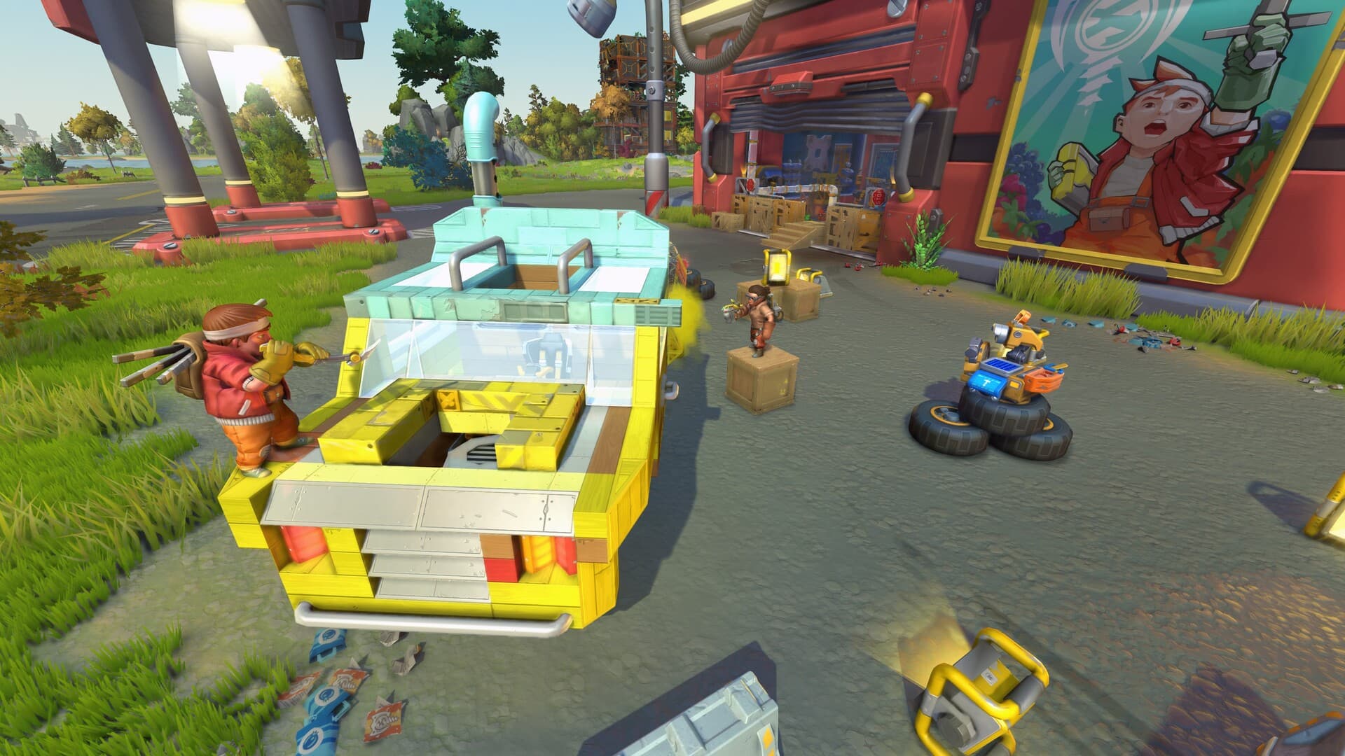
A low-deck hauler for bulky produce cargo, road stability, easy loading, and reliable trader routes.
Logic Build
Piston Elevator - Safe Stops and Service Access
A compact vertical lift with a guided platform, slow test sequence, landing controls, and a reachable emergency stop.